|
SimpleOpt
A Simplified Topology Optimization Programby Michael Miller |
|
Final Presentation
The seminar for this project will take place 2 PM, Wednesday, December 18th, in Altgeld Hall Room 102.Abstract
Current methods of Topology Optimization use series of differential equations to model stress and strain on millions of infinitesimal elements of a single solid. This process is repeated hundreds of times, following one of many optimization algorithms. Clusters of computers working in parallel can take hours to optimize a small part.
The goal of this project is to create a simplified version of the Topology Optimization process. A Java RTICA will be created which uses only basic concepts of physics and mechanics. The RTICA's toy physics will approximate the results of programs that utilize more sophisticated models of physics. The program will consist of three main elements, described below.
What is Topology Optimization?
Topology Optimization is a design process in which three-dimensional, load bearing parts are created with minimal material at maximum strength. In theory, the process is relatively simple.
First, the engineer inputs a current part and the forces that the part will likely undergo. The program then analyzes the stress and strain on each minute element of the part. Areas with low stress are removed, and areas with high stress are reinforced. The program then iterates, continuing to remove and add material until certain criteria are met. For example, the program might stop once all elements have less than a certain amount of stress and iterating again would push them over this limit.
The results of this process are usually asymmetric, organic-looking parts. In the past, these parts extremely impractical to manufacture. However, in an era of 3D printing, companies are turning more and more readily to Topology Optimization to cut back weight and cost from their machines.
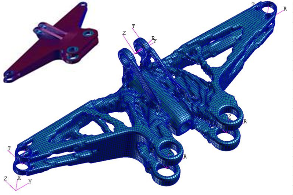
A Part Before and After Topology Optimization
Project Summary
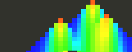
Finite Element Analysis
The FEA calculates the stress at each element in a predefined grid. The analysis starts with an applied force and follows its path downward until it reaches the ground. Each element that receives force distributes it to the three elements beneath it. Often, an element is positioned in a way that its force can never reach ground. In this case, the element is unsupported and the analysis does not apply force to it.
The user can specify the location of forces and the location of the ground. In addition, the user can specify that certain elements are not allowed to have material. These elements are then ignored by the analysis.
FEA Screenshot
(Green in bottom left and right is ground)
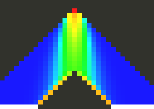
Optimization Algorithm
The program uses a Boundary Layer Optimization algorithm: it evaluates only the edge of the material. The program calculates how much material is currently used and compares this to the predefined goal. If there is more material than required, the program finds the element on the boundary with the least amount of stress and removes it. If there is more material than required, the algorithm reinforces the boundary element under the most stress by adding additional material around it.
Because only edges are evaluated, before the first analysis a grid of material is removed from the entirety of the part to expand the edge and allow for faster optimization.
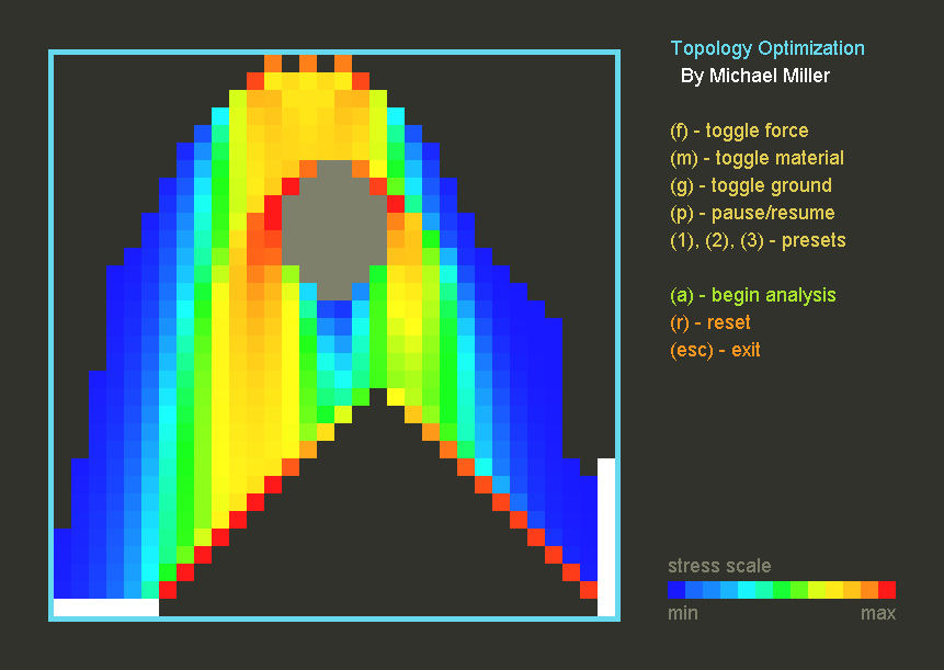
Graphical-User Interface
The GUI provides the user with a number of options. The position and number of forces and ground can be modified and moved, and material can be excluded from analysis. The target amount of material can be adjusted. The analysis can be run at max speed or slowed down to allow the optimization to be visualized.
Screenshots