1 Quadrotor Kinematics
1.1 Section Overview
The kinematics of a flying quadrotor are largely involved with transforming between coordinate frames. A coordinate frame is a term for a frame of reference. Each disconnected object has its own frame of reference. If a person is sitting in a car, the car has a reference frame, and the person has a reference frame. If the car turns then the person necessarily turns with the car. If the person turns the car doesn't change at all.
Coordinate frames can translate and rotate relative to each other. A translated coordinate frame simply moves from one location in space to another, such as a plane moving forward in the air. However a rotated coordinate frame doesn't move within space, but rather rotates around. Think of a plane commpleting a barrel roll maneouver. It can stay in the same place but it rotates in space. And someone looking out of the plane window will see a different view as the plane continues to rotate.
We can generate equations that will give the position and orientation of one coordinate frame with respect to another. Using these equations, we can take data from any coordinate frame and express it in terms of another. This is very important for applications of quadrotors in the real world.
While flying, a quadrotor will often gather data with respect to itself, as from an inertial measurement unit (IMU) on board the machine. This device can track the translational and rotational accelerations of a body These measurements can be used to determine velocity, position, and orientation of the robot. In addition, data can be collected with respect to the fixed world frame, such as from a GPS unit. You can see how it might be difficult to use both of these measurements, because one is based off of what the quadrotor sees, while the other is based off of the quadrotor's position in the world. Fortunately, the equations that we will develop will allow us to resolve these differences and transform the data into a more usable form.
1.2 Translations
Translations are a fairly simple concept to grasp. If two frames have the same orientation (rotation), then the translation of frame 1 with respect to frame 0 is the negative of the translation of frame 0 with respect to frame 1. This is expressed more explicity in the equations seen below.
$$
q^1_0 = -q^0_1
$$
And if a point is expressed in the coordinates of frame 0, such as
$$
p^0 = \begin{bmatrix}1\\0\\0\end{bmatrix}
$$
Then the translation of that point into frame 1 can be expressed as
$$
p^1 = q^1_0 + p^0
$$
But remember that this is for two frames that have the same orientation. The difficulty lies in when one frame is rotated. This changes the above relationship, as the way that coordinates are represented is different from one frame to the next. In order to understand this, we must first explore rotations.
1.3 Euler Angles
In order to understand the way that we think about rotations, we must first explain the concept of Euler Angles. Euler Angles are a way to systematically describe the way in which an object is rotated. It is defined by a sequence of three rotations, each about a coordinate axis.
One of the most common Euler Angle sequences for Aerospace applications is the ZYX sequence. What this describes is that the body is first rotated about the body Z axis in the original position, which also coincides with the world z axis. A demonstration of this is displayed below.
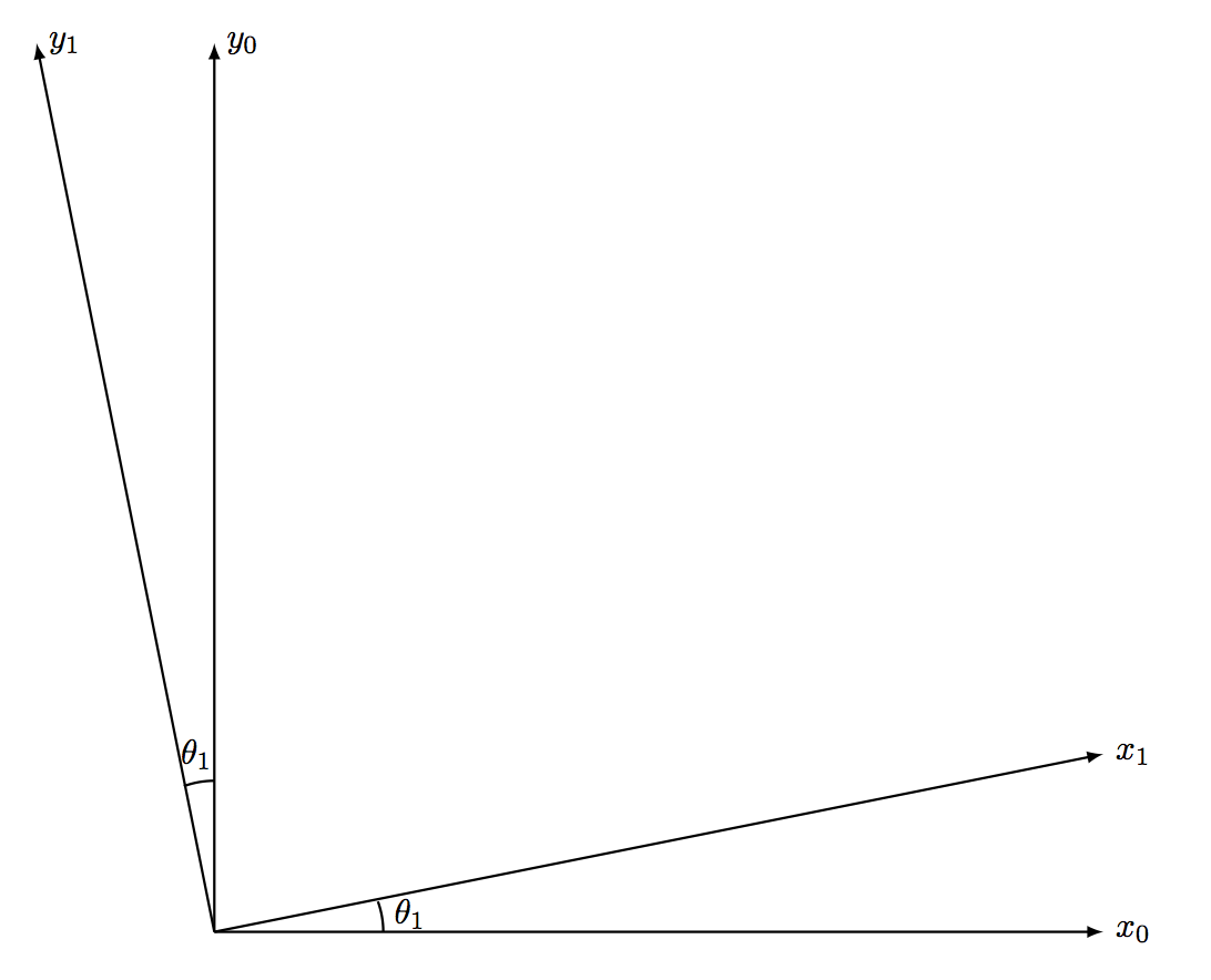
This allows us to express the rotation for the first Euler Angle rotation as the rotation matrix about the Z axis, shown below.
$$
R^1_0 = \begin{bmatrix}
cos(\theta_1)&sin(\theta_1)&0\\
-sin(\theta_1)&cos(\theta_1)&0\\
\end{bmatrix}
$$
Then, the body is rotated about the body Y axis, which is dependant on the original Euler rotation. However, taken independantly, we are able to write the rotation matrix much like for the Z rotation, which can be seen below.
$$
R^2_1 = \begin{bmatrix}
cos(\theta_2)&0&-sin(\theta_2)\\
0&1&0\\
sin(\theta_2)&0&cos(\theta_2)
\end{bmatrix}
$$
Finally, the body is rotated about the body X axis, which is dependant on the preivious two rotations, to yield the rotation matrix
$$
R^3_2 = \begin{bmatrix}
1&0&0\\
0&cos(\theta_3)&sin(\theta_3)\\
0&-sin(\theta_3)&cos(\theta_3)
\end{bmatrix}
$$
By multiplying these matrices together, in the sequence that they are taken, yields a final rotation matrix from the world frame to the body frame dependant on only the Z, Y, and X Euler Angles, which in Aerospace are called Yaw, Pitch, and Roll, respectively.
$$
R^3_0 = R^3_2R^2_1R^1_0\\
R^3_0 = \begin{bmatrix}
c_1c_2&c_1s_2s_3-s_1c_3&c_1s_2c_3 + s_1s_3\\
s_1c_2&s_1s_2s_3+c_1c_3&s_1s_2c_3 - c_1s_3\\
-s_2&c_2s_3&c_2c_3
\end{bmatrix}
$$
Where c1 and s1 represent cosine and sine of the first Euler rotation about the Z axis.
1.4 Rotations
With a rotation matrix able to transform a point from one frame to another, and back again. Utilizing this rotation matrix, we are able to express a point in one frame relative to another via the equations below.
$$
p^j = q^j_k + R^j_kp^k
$$
Notice how with 0 Euler Angles, \( R^j_kp^k \) is just the identity matrix, and the pure translational equation is recovered. This is a good verification that our model behaves as we intuitevely think that it should.
1.5 Putting it Together
With our equations, we can now put everything together to express one point given in one frame in the coordinates of another. With careful application of algebra, we recover the equations seen below
And we can use these equations to show the frames.
Using this application, explore the way that a coordinate frames are expressed with respect to one another. Use the controls shown to translate and rotatate the body, and see what happens from the quadrotor's point of view.